

Why the compressor, not the blaster, decides what you can clean and how fast
When people talk about dry ice blasting, the machine itself often gets the credit for the cleaning power. In reality the blaster is only half of the system. The compressed air behind it provides the energy, and the quality, pressure and volume of that air determine the result. Getting the air right is the single most important step in setting up a dry ice cleaning job.
The blaster adds nothing but pellets
A dry ice blaster does not create or generate power. All it does is take dry ice pellets from one location, the hopper, and feed them into the airflow. The principle is simple: what goes in comes out. That means air, pellets and, if the air is not clean, water.
If the supply air is contaminated or contains water, an air handling or air preparation unit should be fitted, together with a water separator and oil/water filters where needed. The pellets also have to leave the rotor plate easily, and clean, dry air helps to keep that flow steady.
Pressure and volume do different jobs
Two properties of the air matter, and they should not be confused with one another.
- Pressure is what you can clean. Low pressure suits delicate cleaning, while high pressure is what you need for tasks such as paint stripping.
- Volume is how quickly you can clean. Taking a low-volume setup as a speed of 1, a high-volume setup works at roughly 5 to 7 times that speed.
A job that needs gentle treatment can still be done quickly if there is plenty of air volume available, and a high-pressure job will be slow if the compressor cannot keep up with it.
Sizing the compressor
As a rule of thumb, 1 kW of compressor power delivers around 200 litres of air per minute. In horsepower terms, 1 HP (0.75 kW) equals about 150 litres per minute, or 5.3 CFM. The table below shows typical compressor sizes at a working pressure of 7.5 bar (110 psi), together with the electrical supply each one needs.
| Electrical supply | kW | HP | Bar | Psi | m³/min | CFM |
| 16 A – 3 phase – 400 V | 11 | 15 | 7.5 | 110 | 1.6 | 56 |
| 32 A – 3 phase – 400 V | 22 | 30 | 7.5 | 110 | 4.0 | 140 |
| 64 A – 3 phase – 400 V | 45 | 60 | 7.5 | 110 | 8.0 | 280 |
| 128 A – 3 phase – 400 V | 90 | 120 | 7.5 | 110 | 18.0 | 630 |
The delivery figures in the table come out a little lower than the rule of thumb for the smaller units, so it is safer to size from the table where possible. The electrical supply matters just as much as the air output: the larger machines need a 64 A or 128 A three-phase connection, which is not available at every site.
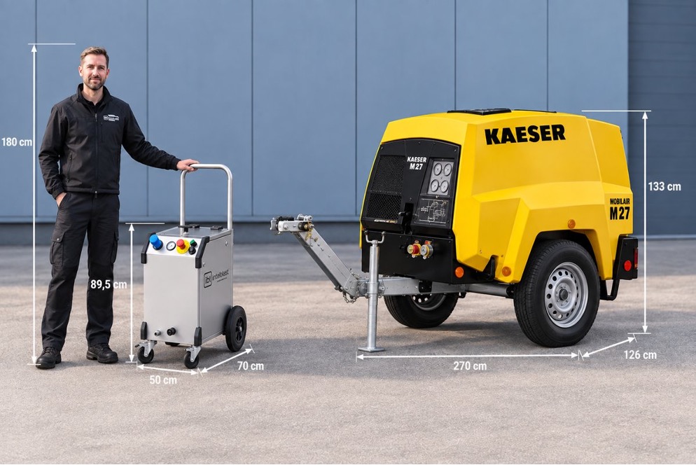
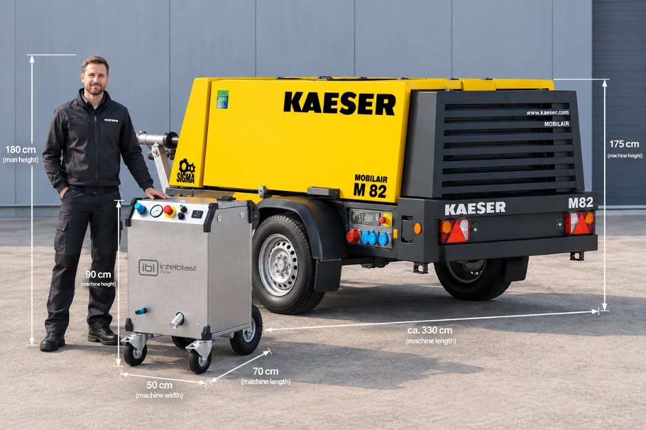
Compressors of this size are also physically large compared with the blaster they feed. The comparison below places a blaster of roughly 90 cm high, 50 cm wide and 70 cm long next to two mobile compressors. The smaller compressor measures about 270 cm in length and 133 cm in height, and the larger one about 330 cm in length and 175 cm in height. Transport and working space need to be planned accordingly.
Preparing the air in a fixed installation
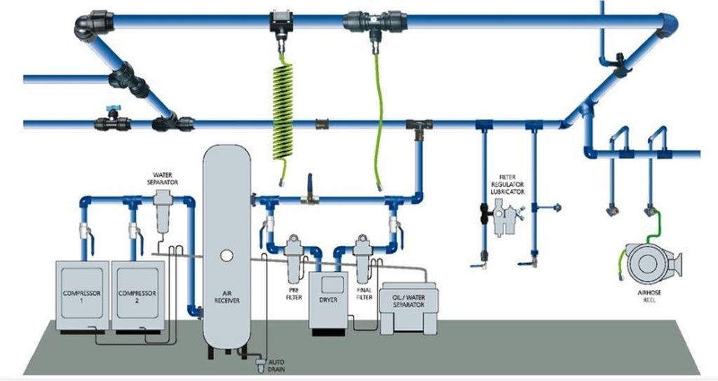
In a permanent compressed air system, the air passes through several stages before it reaches the blaster. The layout shown in the diagram below includes compressors with water separators, an air receiver with an automatic drain, a pre-filter, a dryer, a final filter and an oil/water separator. Filter, regulator and lubricator units can then be placed at the points of use.
The diagram also marks two set-ups with a red cross, a coiled hose and a hose reel, showing them as arrangements to avoid.
Choosing the right pressure for the application
The right working pressure depends on the surface and the contamination. Delicate electronics and historical masonry call for low pressure, while coatings and resins can take far more. The table below gives recommended ranges for common applications.
| Application | Typical items | Recommended pressure | Notes |
| Industrial equipment | Motors, pumps, compressors, gearboxes, conveyors | 100–150 psi (7–10 bar) | Standard industrial cleaning |
| Electrical and electronic equipment | Control panels, circuit boards, generators | 30–70 ps i (2–5 bar) | Power off and ground the equipment |
| Automotive and aerospace | Engines, transmissions, aircraft parts | 80–150 psi (5.5–10 bar) | Avoid delicate composite surfaces |
| Food and beverage | Ovens, mixers, conveyors, packaging lines | 60–120 psi (4–8 bar) | Food-safe, no residue |
| Plastic and rubber molds | Injection molds, tire molds, extruders | 100–180 psi (7–12 bar) | Removes residue without abrasion |
| Printing | Rollers, ink trays, press components | 70–120 psi (5–8 bar) | Effective ink removal |
| Fire and smoke remediation | Walls, brick, wood, metal surfaces | 30–120 psi (2–8 bar) | Removes soot and char |
| Historical restoration | Stone, brick, wood beams, monuments | 40–90 psi (3–6 bar) | Use low pressure to prevent damage |
| Marine | Engine rooms, bilges, deck equipment | 100–150 psi (7–10 bar) | Degreases without abrasion |
| Adhesive, paint and resin removal | Paint, epoxy, sealant, gaskets | 120–250 psi (8–16 bar) | Aggressive cleaning for coatings |
Key takeaways
- The blaster only feeds pellets into the air stream. The compressed air supplies the power.
- Clean, dry air protects the system. Use air preparation, water separators and oil/water filters where the air is contaminated.
- Pressure determines what you can clean, and volume determines how fast you can clean it.
- Size the compressor for both: check the air volume it delivers and the electrical supply it needs.
- Match the pressure to the application, from 30 psi (2 bar) for electronics up to 250 psi (17 bar) for paint and resin removal.
FAQ
If you have questions then please feel free to visit our comprehensive FAQ list
Intelblast suppliers of compressors:
Kaeser
www.kaeser.com
Atlas Copco
www.atlascopco.com
Ingersoll Rand
www.ingersollrand.com
Compare
www.compair.com